Ezward on GPS
Stuff I've learned about using GPS
Donkeycar meets RTK GPS 🔗
I want to race RC cars. I don’t want to actually drive them. I’d probably suck at it. I’m really pretty sure about that. So they have to drive themselves. There are a bunch a ways to get an RC to drive itself. When you are outside gps is a good choice, but it has to be the right kind of gps and it must be setup the right way. You also need software to read and interpret the data sent by the gps. My automonous RC car uses the DonkeyCar framework for small scale car racing, so I’m adding gps support to that framework. An autonomous car also needs a computer to run the software. DonkeyCar supports the Raspberry Pi or the Nvidia Jetson Nano as the brains of the car. I’ve tried both, but It turns out that the Raspberry Pi works a little better, but either can work. I’ll talk about both.
 A
A We Don’t Need No Stinking Camera 🔗
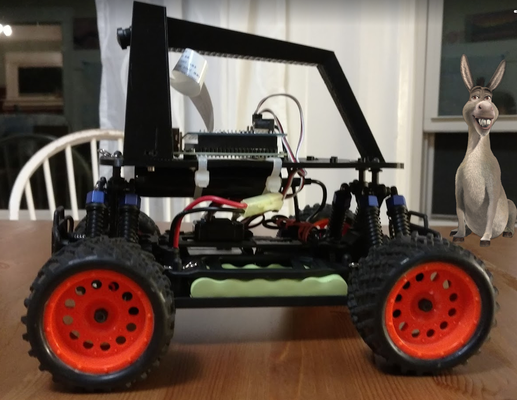
The original DonkeyCar approach of using a single camera and a neural network for auto-pilot works really well, especially indoors where lighting conditions can be controlled. It is more difficult to use outdoors because lighting conditions change dramatically from day to day and even over a single day as shadows or clouds evolve. But outside under the vast blue sky (ooh, pretty) we have access to something we don’t have inside - GPS Satellites.
 A GPS DonkeyCar
Send in the Satellites 🔗
Lets talk about gps satellites. The term GPS (Global Positioning System) is commonly used to refer to satellite positioning systems generally, but technically it refers to the to American system of positioning satellites provided as a service of the United States government. Other systems have been added (generally also by governments). The Russian government provides the GLONASS system; China provides the BeiDou system and the European Union provides the Galileo system. There are other smaller regional systems, some based on a combination of satellites and land based installations. Collectively these are often referred to as the Global Navigation Satellite Systems (GNSS) system. The more the merrier; literally, if you get happy about coverage, accuracy and speed. In this discussion I’ll use lower case gps or GNSS to refer to these systems collectively and upper case GPS to refer specifically to the American system.
So the gps receiver (more below) gets radio signals from the gps satellites. Each satellite is transmitting a very exact time and it’s current position in space. When the gps receiver gets a time and satellite position, it calculates how long it took the signal to reach the receiver and can then calculate the distance to the satellite. With 3 satellites the receiver can triangulate it’s position on the surface of the Earth. The reality is a little more complicated because the receiver uses many satellites and the Earth is not flat (glad I got that off my mind), but you get the idea.
NEO ZED Blox What? 🔗
Next, let’s talk about the kinds of gps receiver devices available for talking to the satellite systems. Since the American GPS system was first, early chips only talked to it. Then when GLONASS came online chips came out that supported both GPS and GLONASS, even simultaneously. Newer chips support GPS, GLONASS, BeiDou and Galileo and some of the smaller systems. The most popular devices are based on chips created by a company named U-Blox. They have lots of different GPS chips for various purposes and with varying capabilities. Their latest chips are series 10. You can still find series 6, 7, and 8 out there. The series 8 chips are much better than 6 or 7; they support more kinds of satellites and more simultaneous satellite connections. The U-Blox series 9 chipsets are much better than any of the prior series.
The SparkFun GPS Breakout - NEO-M9N, SMA (Qwiic) is a $75 GPS receiver with a million dollar name. More importantly for our purposes, it provides +/- 1.5m accuracy, which is good enough for many scenarios including a single lap RC car race. It has a USB port, so it is very easy to interface to the RaspberryPi or Jetson Nano, and it has an SMA connector so you can use a good antenna with a ground plane (more on that later). This board also shows a nice feature of the Sparkfun line; the pass-through I2C bus using the 4-pin Quiic connectors, so you can communicate to the board over I2C if you don’t have a free USB port.
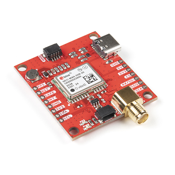 SparkFun GPS Breakout - NEO-M9N, SMA (Qwiic)
I’m using a a different device from Sparkfun with a series 9 chipset, the SparkFun GPS-RTK-SMA Breakout - ZED-F9P (Qwiic). The name really rolls off the tongue doesn’t it? Catchy. Anyway, the ZED-F9P chipset is a big improvement over the NEO-8 series because it supports yet more satellite systems, more simultaneous connections and most importantly, it supports a second frequency band (L2) for higher precision measurements (so you need an L1/L2 dual band antenna). Newer is better. Ask any baby.
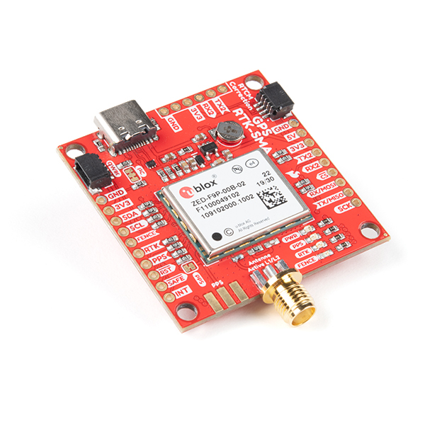 SparkFun GPS-RTK-SMA Breakout - ZED-F9P (Qwiic)
Other companies produce receiver boards using the same U-Blox ZED-F9P chipset. ArduSimple makes a number of different boards. This one includes the dual-band L1/L2 antenna and still costs a less than the SparkFun board without the antenna. You can also get this one with the headers presoldered if you don’t like melting metal for fun. With the pass-through headers, it can be mounted on an Arduino Uno.
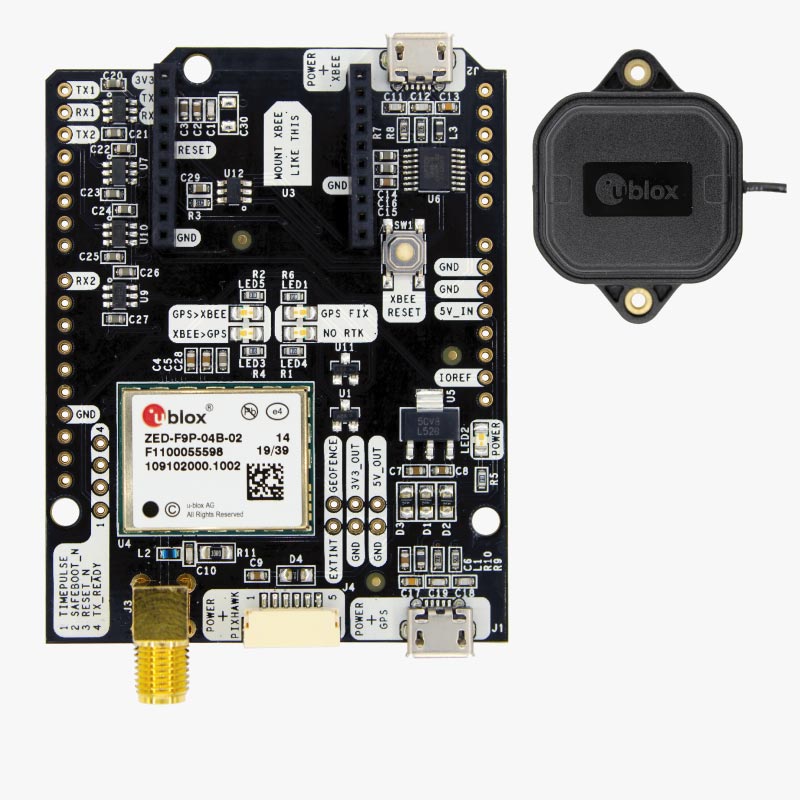 ArduSimple AS-STARTKIT-BASIC-L1L2-NH-02
What is it with these product names? Anyway, U-Blox isn’t the only game in town; you can find inexpensive GPS modules that use other chipsets, often from China. In many ways these can work interchangeably with U-Blox based boards because they all support the a standard way of reading data from the satellites, call NMEA sentences. This is a line-oriented text protocol. So if your software can parse NMEA sentences then it can work with most gps modules. You can find the NMEA parser I wrote for DonkeyCar here.
U-Blox does have an ace up its’ sleeve relative to other chipsets; it provides a piece of software called U-Center that can be used to configure and operate U-Blox based devices. It allows you to optimize the way the chipset works for how you want to use it, within limits. U-Center is written for Microsoft Windows, but it can be run on Macintosh or Linux using the Wine emulation system. I’ve successfully done this on Macintosh by following this ArduSimple forum post. SparkFun has a good introduction to U-Center.
How accurate is gps? 🔗
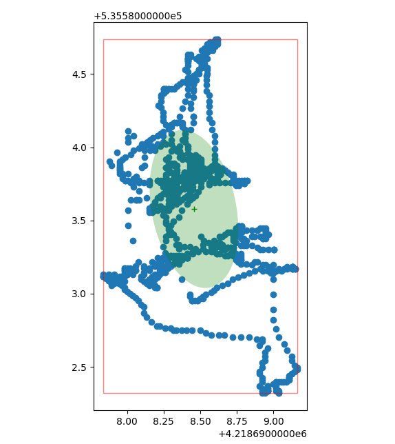
Good question. Here is the crappy answer: it depends. Let’s just assume you have a great view of the sky; then GPSInsight suggests that gps should yield an accuracy of 2 meters CEP (Circular Error Probability); that means that 50% of readings will fall within a circle with a radius of 2m. The other 50% will be outside. This is a bit of a weird way to measure accuracy of gps (nevermind that this was developed as a a measure of accuracy for ballistic munitions); CEP assumes a Guassian error distribution. However, if you make a whole bunch of readings over a period of time while staying in one place, you will notice that the errors are not randomly distributed around a center; they are more like a random walk. In fact, the error is not really random; much of it is caused by 2 factors; pertubations in the GPS satellites’ orbits and ionopheric/atmospheric changes over time. Neither of these effects are random; they change systematically over time and so cause the position to look like it is moving on a path, even though you stay in one place. This is called GPS drift. Here is a chart I created using the gps code I created for DonkeyCar. It represents 1 sample per second for 100 seconds recorded using a cheap ($10) GPS receiver (something equivalent to a U-Blox 6 or 7 series).
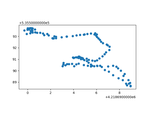 Gps position readings over time while staying in place; 1 sample per second for 100 seconds
These positions are in UTM units; essentially the position in meters on the surface of the earth. You can see the readings span about 5 meters vertically and 8.5 meters horizontally. If we averaged all of these points we would get one measure of the center (the centroid); then we could find the 50 points closest to this center; that would be the CEP.
But the important point is that these are not randomly arranged around the center; instead the position reading is moving around over time like it is walking. Think about this if you are relying on gps readings in order to know where your autonomous car is located; beyond the fact that readings are +/- 4 meters from center, at any given time if you take a few readings it may appear you are quite near a given point, but that is a false assumption. If you keep taking readings it will appear as if you are moving. If you average the readings your position will get more accurate, but not in the same way it would if the error was a Guassian distribution around a center. So taking a few readings and averaging them is not going to work, and it would be way too slow for racing.
The quality of the GPS receiver and it’s antenna can mitigate this drift; a higher quality setup will use more satellites, more satellite systems and more satellite frequency bands. Using more satellites minimizes the effect that any single satellite’s error will have. Different radio frequencies are affected differently by ionospheric/atmospheric changes, so muliple frequences mitigates these effects. All of the extra information can be used to produce more accurate and stable position estimates. All of the extra technology can be used to charge you more money :(
Here are 1000 readings taken with an U-Blox NEO M8N with an active GPS/GNSS antenna and a good ground plane mounted on a tripod (basically, a good setup; more on antennas and ground planes later).
 U-Blox NEO M8N position readings over time while staying in place; 1 sample per second for 1000 seconds
The points are within A 5 meter range in each direction. So that is better than the first figure, which was done with a non-active antenna and no base plane.
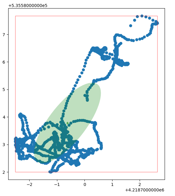
Next, this is 1000 readings with a U-Blox ZED F9P, an active GPS/GNSS antenna and a good ground plane mounted on a tripod, the same setup as the last set of readings.
 U-Blox ZED F9P position readings over time while staying in place and no RTK; 1 sample per second for 1000 seconds
The points are within a 2.5 meter range vertically and 1.25 meters horizontally. So that is much better than the NEO-N8M. This shows the series 9 chipset is superior to the series 8. But is this good enough for an RC race? Maybe, if your race is short and the race track is a couple of meters wide. Let’s say that a single lap around the track takes 20 seconds; take any 20 consecutive points in the figure above and determine the min and max in that set; I can’t find a set of 20 points where the range is more than about 0.6 meters. That means that in 20 seconds your position will drift no more than 0.6 meters. That may be good enough for a single lap. But what if your racetrack is longer and what if the race is multiple laps? You might end up navigating off the track before the race finishes. Crap, we are out of luck I guess. But wait, there is more!
Kinematifanatics 🔗
What if you could make readings that were more like 2 centimeters CEP? What if you could do that 10 times per second while you were moving? What if it was cheap as hell? Well, forget that last one, but the other two are possible by using RTK gps. Sparkfun describes RTK gps, “RTK is short for real time kinematics. A GPS receiver capable of RTK takes in the normal signals from the Global Navigation Satellite Systems. On top of these signals an RTK receiver takes in an RTCM correction stream and then calculates your location with 1cm accuracy in real time.”
What are these magical ‘corrections’ they speak of and who conjures them? Corrections are created by Earth-bound base stations and then transmitted to the gps receiver. Think about corrections this way; a gps receiver uses the time stamps and orbital positions it gets from the satellites to triangulate it’s otherwise unknown position on the Earth. But the base stations already know their position; their position has been very, very, very, very carefully measured. Base stations already know where they are, but they can also talk to the satellites and do the triangulation thing. If the triangulation calculation yields an incorrect position, then base station can calculate the difference between where it knows it is and where triangulation says it is; that is a correction. The base station can then send that offset to our gps receiver, then our gps receiver can apply the offset after it triangulates its position using the satellites, thus making the result much more accurate. This works if you are pretty close to the base station that is broadcasting the corrections (say within about 35km) and if you apply very recent corrections. This make sense if you think about the things that cause drift; if you are close to the base station then you are able to see the same satellites and you are subject to similar atmospheric conditions. You need recent corrections so that not much drift has occurred between calculating the correction and applying the correction.
For reals, the way corrections are calculated is much more complicated than how I have explained it, but you get the idea.
Please correct me 🔗
There are many organizations that maintain base stations and provide corrections over the Internet. The corrections are typically broadcast over the internet using a protocol called NTRIP; in this case the server is called an NTRIP Caster. The actual corrections are commonly in a format called RTCM3. You typically must sign up for a free account to get access to the NTRIP caster servers. I have at least 4 base stations in the UNAVCO network near me. There is also a network maintained by individuals good enough to share their gps data for free; RTK2Go. Resources are changing and improving all the time; check this global list of organizations that host NTRIP servers; rtcm-ntrip.org.
You basically find an organization that covers your country or region and lookup their list of servers and locations. If they have one with 35km of you then you are in luck; sign up with them for an account to get access to the servers, then configure your NTRIP client sofware using the information they provide (I tell more about client software below).
All our base are belong to you 🔗
What if you don’t have a fixed base station near enough to you? That’s simple; create your own. It’s possible to use a second RTK gps receiver as a base station. One issue with that is that your base station does not have a very, very, very, very carefully measured position. However, you can let the base station sit there for a while and get lots and lots and lots of readings so it calculates a very good estimate of its position. Good enough for our needs.
Sparkfun has a very detailed walkthrough on how to setup your own RTK base station.
Client Tell 🔗
Ok, so we have a source of RTCM3 corrections, maybe sent over the Internet using the NTRIP protocol, but our gps receiver doesn’t know anything about the Internet; it has serial ports (how 1980s) for communication. How do we get the RTCM3 corrections to the gps receiver’s serial ports? Well we first need an NTRIP client to receive the RTCM corrections, then we write those corrections to a serial port on the gps receiver board either using a direct connection to the RaspberryPi/Jetson Nano or via a radio connected a ZED-F9P serial port.
The ZED-F9P has several serial ports. There is a serial port associated with the USB connection; this is very easy to use. There are two other serial ports to which header pins can be soldered (so less easy). Remember that picture of the Sparkfun-ZED-F9P-stupid-long-name-thing above; look for the connections marked RX2/TX2; those are the receive/transmit pins respectively of the serial ports. This is clearly explained in the Sparkfun hookup guide. It also explains about antennas and ground planes and other setup stuff, including connecting to a corrections source, but we’ll talk about that here as well.
So receiving the corrections; our Donkeycar has a RaspberryPi (or a Jetson Nano) and that has Wi-Fi. So if the car is close enough to a Wi-Fi hotspot then it can use an NTRIP client to read the RTCM3 corrections from the base station over the internet, then send the corrections to the gps receiver over a serial connection. If the car is not consistently close enough to a Wi-Fi hotspot (which it probably won’t be), then you could use cellular data; I taped my phone to my car and put it into hotspot mode, then connected the RaspberryPi Wi-Fi to the phone’s hotspot so it could access the Internet while it was driving.
A RaspberryPi also has Bluetooth and so does our phone. So another way to get corrections using your phone is to get an NTRIP client mobile app on the phone and use it to get the corrections from a base station, then transmit the corrections to the RaspberryPi using Bluetooth serial. The RaspberryPi would then forward the corrections to the gps receiver over a serial connection.
But what if you have to use your own base station rather than a publicly available NTRIP server? That might actually be the easiest scenario, but the most expensive. In that case need a second RTK gps device to act as the base station; a device that can create RTCM3 corrections. Then we still have the problem of getting the corrections from the base station to the gps receiver. We could go through the RaspberryPi; maybe connect a Bluetooth radio to the serial output on the base station and have it received by the RaspberryPi’s Bluetooth, then the RaspberryPi can forward it on to the gps receiver via a serial connection. Alternatively we can cut the RaspberryPi out of the picture altogether; we can connect a radio transmitter base station gps’ serial ports and a compatible radio receiver to the donkeycar gps’ serial port; the base station transmits the RTCM3 connections via radio transmitter and they go directly to the gps receiver via it’s radio. That is a common way to do this; see Tom Coyle’s article Using the Donkey Car Path_Follow Template with RTK GPS on DIYRobocars for a working example. There are various radio technologies that could be used, but the best is LoRa. LoRa radios have long range, which is good for us because it can cover a large track. Further, a LoRa transmitter can be configured in broadcast mode so many LoRa receivers can listen for the data at the same time. That works really well at a track with multiple competitors.
The Secret Software Sauce 🔗
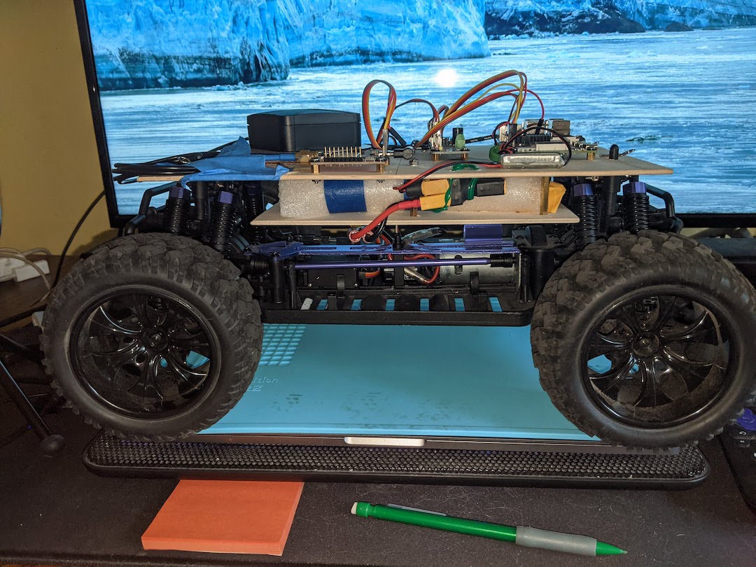
Ok, this is the section (maybe sections) where I’ll give detailed instructions on how I accomplished getting RTK gps to work on a Donkeycar. Hopefully it will help you avoid a bunch of the experimentation I had to go through and make things faster for you. First a pretty picture to set the mood.
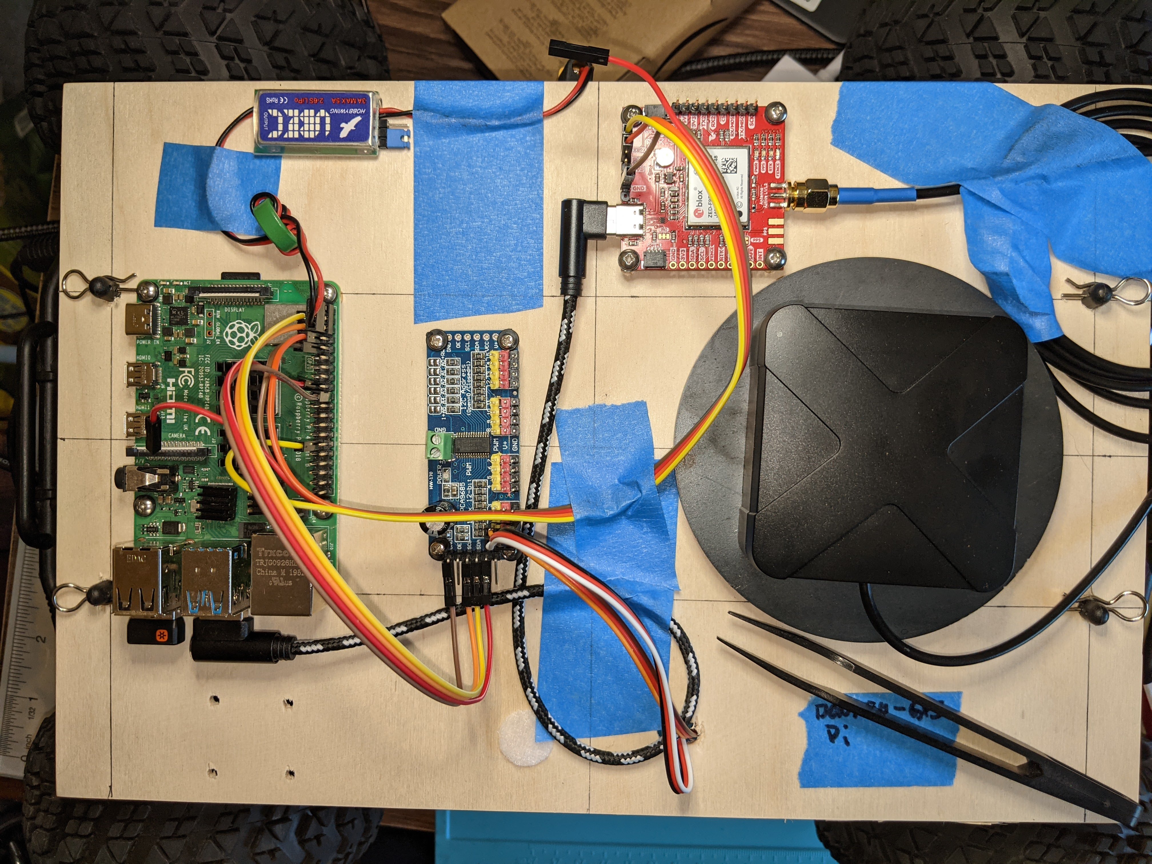 DonkeyCar with Sparkfun RTK GPS
So much blue tape. Anyway, the picture shows a DonkeyCar with a RaspberryPi connected to a Sparkfun ZED-F9P RTK GPS board via USB and GPIO serial. In this case it is using an extra hardware backed UART (uart3) mapped to pins on the gpio bus. This was required for reasons explained later. So in this setup we want to get corrections into the RaspberryPi, either using RTKLIB or via an Android NTRIP client, and then send them via a serial port to the ZED-F9P. We then use a second serial port to read (the now much more accurate) NMEA sentences. The following sections describe how to setup the software to do that.
U-Center 🔗
You will want to do 4 things with U-Center to get your gps module setup.
-
Install U-Center
- Windows Installation
- Download in the U-Blox site and run the installer.
- On windows you may need to install a driver so that the gps device is seen as a serial device so you can control it with U-Center.
- See the ‘Update Driver’ section of this Sparkfun tutorial
- MacOS/Linux Installation
- Download and install XQuartz
- Download and install PlayOnMac Windows emulation
- Download U-Center installer for F9P, then double-click on it to install into PlayOnMac.
- Start PlayOnMac if it is not already started, then create a U-Center configuration.
- Map your Mac’s serial device to a COM port in PlayOnMac
- Determine serial port’s device path.
- sometimes it is easier to do this in two steps. (1) Before you plug-in your GPS receiver into the USB port, list the tty devices
ls /dev/tty*(2) Plug your GPS receiver into the USB port and list the tty devices again. The new tty device is your USB port. Take note of the path. Mine was/dev/tty.usbmodem14101.
- sometimes it is easier to do this in two steps. (1) Before you plug-in your GPS receiver into the USB port, list the tty devices
- Create a symbolic link to the device in the PlayOnMac U-Center configuration
dosdevicesfolder. The folder was at~/Library/PlayOnMac/wineprefix/U_Center_/dosdeviceson my machine. To create the symbolic link from the device tocom1execute this command line in a console:ln -s /dev/tty.usbmodem14101 ~/Library/PlayOnMac/wineprefix/U_Center_/dosdevices/com1 - Update the system registry in the PlayOnMac U-Center to include the com port.
- Open the system registry file in a text editor (use a code editor and not a word processor). My system registry file was at
~/Library/PlayOnMac/wineprefix/U_Center_/system.reg. - Find the section
[Software\\Wine\\Ports]and add the line"com1"="/dev/tty.usbmodem14101”, using the com port and device path you used in the symbolic link. Mine section ended up looking like this;[Software\\Wine\\Ports] 1663982657 #time=1d8cfb45d70ce78 "com1"="/dev/tty.usbmodem14101"
- Open the system registry file in a text editor (use a code editor and not a word processor). My system registry file was at
- Save the file. Now when you run U-Center from within PlayOnMac you should have
com1available in theReceiver/Connectionmenu. - Here is a video that shows this procedure Running U-Center on MacOS
- That procedure was adapted from the standard Wine procedure shown in this video
- Determine serial port’s device path.
- Windows Installation
- Launch U-Center and connect to the gps receiver.
- Open the
Receivermenu, then theConnectiondialog and select the COM port that the gps receiver to which the gps receiver. U-Center seems pretty smart about showing the port that is most likely the gps receiver. - Open the
Receivermenu, then theBaudratedialog and set the baudrate to match your gps receiver. If the ZED-F9P is still in its default state, then the baudrate should be 38400. If you have a knock-off gps receiver then it’s probably 9600 baud. RTFM if you can’t figure it out. - Once the COM port and baud rate are set then U-Center should connect with the GPS and display received data in the data view window. If nothing appears, check your connection and serial port parameters.
- Open the
- You will want to increase the default baud rate on the serial ports.
- Start U-Center and connect your gps receiver to your computer that is running U-Center as described in (1) above.
- Open the
Viewmenu, then theConfigurationview and choose thePRT (ports)port configuration. - Update UART1 and UART2 to 115200 baud, selecting the
Savebutton after each change. This will update the gps module’s live (ram) settings, but not write it to flash.- If you are connected via either of these ports and telemetry from gps board stops, then go to “Receiver -> Baud rate” menu in the main window and select the new baud rate there. Confirm that NMEA messages in the Text Console resumed updating (meaning that u-center has successfully re-established the communication with the device at the new baud rate), then continue.
- Select the
Closebutton and u-center will ask if you want to save the settings to flash, allow it to open the save dialog, then choose theSavebutton and the changes will be written to flash so that the are applied each time the gps module starts.- Note that some gps receivers, like the SAM-M8Q, so not have flash. Instead they have battery backed memory. So they won’t save to flash, but you settings should stay intact as long as the battery is charged.
- You will want to increase the rate at which the gps receiver outputs position estimates. By default, most gps receivers only output one per second. That is a little slow for racing, so we want faster position updates. The ZED-F9P Data Sheet indicates that the max rate is 7hz when using 4 satellite systems, 10hz when using 3 satellite systems and 15hz when using two satellite systems. More simultaneous satellite systems is more accurate, but slower. We will take the compromise of 10hz. Note that the NEO-8 is limited to an update rate of 5hz in order to maintain contact with two satellite system.
- In u-center, open the
Viewmenu, then theConfigurationview and then theRATE (rates)dialog. - Set the
Measurement Periodto 100ms to get a 10 hz update rate (NEO-8 owners should use 200ms for 5hz). - Select the
Savebutton to save to the gps module’s live settings to ram. - Select the
Closebutton and u-center will ask if you want to save the settings to flash; allow it to open the save dialog, then choose theSavebutton and the changes will be written to flash so that the are applied each time the gps module starts.- Note that some gps receivers, like the SAM-M8Q, so not have flash. Instead they have battery backed memory. So they won’t save to flash, but you settings should stay intact as long as the battery is charged.
- In u-center, open the
- If you are using RTK gps, you will also want to increase the resolution of the position values in the NMEA messages. RTK outputs a higher resolution position than standard NMEA can handle (it doesn’t provide enough decimal places in the position values), we we want to change that.
- In u-center from the
Viewmenu, open theConfigurationview and choose theNMEAconfiguration. - In the
Mode Flagssection, check theHigh Precision Modecheckbox. - Select the
Savebutton to save to the gps module’s live settings. - Select the
Closebutton and u-center will ask if you want to save the settings to flash; allow it to open the save dialog, then choose theSavebutton and the changes will be written to flash so that the are applied each time the gps module starts.- Note that some gps receivers, like the SAM-M8Q, so not have flash. Instead they have battery backed memory. So they won’t save to flash, but you settings should stay intact as long as the battery is charged.
- In u-center from the
U-Center can also be used to test your NTRIP server settings.
- Start U-Center and connect your gps receiver to your computer that is running U-Center as described in (1) above.
- If you have an RTK gps receiver, then connect to your NTRIP server.
- Open the
Receivermenu, then theNTRIP clientdialog. - In the
NTRIP client settingsdialog enter the NTRIP server’s address and port. You can get these from the organization’s website. For instance, the UNAVCO server is at addressrtgpsout.unavco.organd port 2101. - Next input your username and password for the server. You should have gotten this when you signed up for an account with the organization. For instance my UNAVCO username and password is ‘imnotthat’ and ‘stupid’.
- Finally you need to specify the NTRIP mount point for the server you plan on using. Again, your organization’s website should have a listing of the available mount points (these are the base stations by another name). Pick the one that is closest to you. You should be within 35km for this to work well. Note that you can pull down the list of mount points by selecting the
Update source tablebutton; it will ask the server for all the mount points. You can select a mount point from the list. You can see details about the available mount points; choose theMount point detailsbutton. When I did that I noticed the mount point I use only connects to GPS and GLONASS satellites; that makes me want to go back and change my RATE to 15hz since I am only getting corrections for those two satellite systems. - Once you have entered the server address, port, username, password and mount point, select the
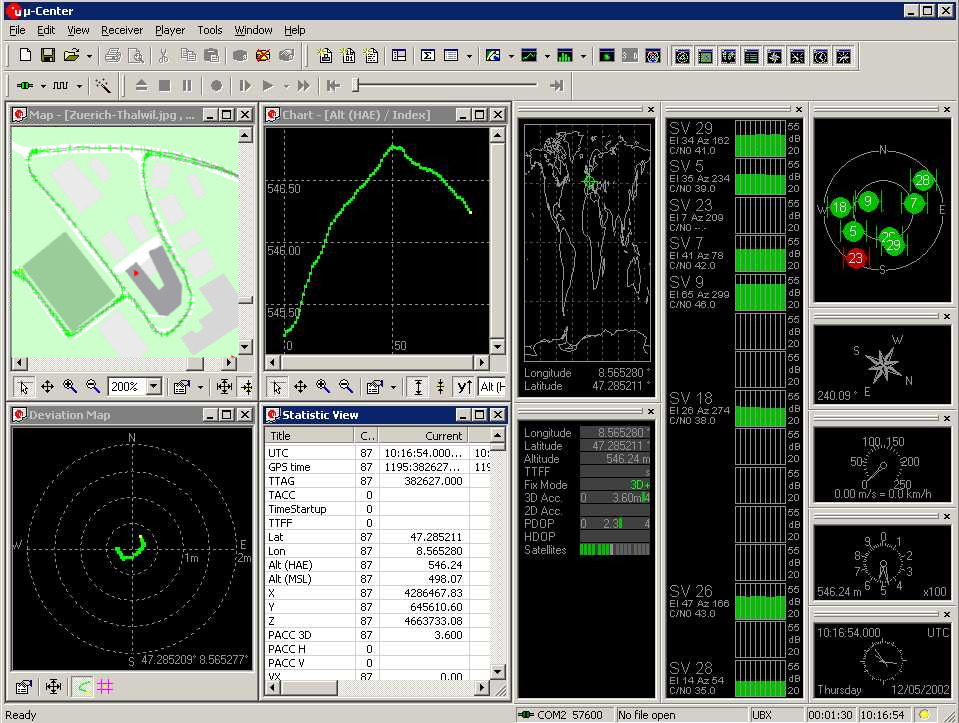
OKbutton. At this point U-Center should connect to the NTRIP server and start downloading corrections and then sending them to the gps receiver. - As corrections are applied you should see the LED on the ZED-F9P transition from solidly lit to blinking. Notice also that in U-Center, on the right, there is a panel that shows various data, including 2D accuracy and Fix mode. As the fix improves, fix mode will go from
2D, to3D, to3D/DGNSSas more satellites are acquired. When corrections can be applied the fix mode will transition to3D/DGNSS/FLOATand finally3D/DGNSS/FIXED; at that point you should see very high accuracy.
- Open the
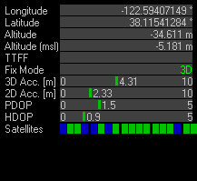 U-Center accuracy
The meaning of the Fix Mode status in U-Center:
- “3D” fix mode: 3m CEP accuracy, no RTK
- “3D/GNSS” fix mode: 2.5m CEP accuracy, no RTK
- “3D/DGNSS/Float” fix mode: 20cm CEP, RTK position stabling
- “3D/DGNSS/FIXED” fix mode: 2cm CEP, RTK position stabled
RTKLIB 🔗
U-Center is a Windows GUI application; it is not suitable for running on our RaspberryPi or Jetson Nano, so we need another way to read corrections from our NTRIP server. RTKLIB is an open source software package written by Tomoji Takasu, that can use GNSS raw data to run real-time or post-processing solutions to accurately determine relative position using differential information from two receivers (RTK/PPK). RTKLIB has way more capability than we will be using. We really only need one of it’s command line utilities; str2str (stream to stream). str2str can connect to an NTRIP server and then write the corrections to up to 4 outputs. It can convert formats if that is necessary; so it could take in RTCM2 corrections, but output RTCM3 corrections.
- http://www.rtklib.com/
- RTKLIB github
- RTKLIB Demo5; rtklibexplorer RTKLIB fork
Compile RTKLIB on RaspberryPi/Jetson Nano 🔗
We can build RTKLIB use it to request corrections over the internet and send them to a serial port. We only need the str2str command line application, so we will only build that.
You must have the GCC compiler and the make build utility available. These are pretty much always available on a Linux system. However for MacOS you must install the XCode toolset; so first, open the Mac App Store and install Xcode for free. Then, open Xcode, go to Xcode menu (on the menu bar) > Preferences > Downloads, and install Command Line Tools. You will get commands like gcc, make, purge… Windows is an inhospitable place for gcc, but you can give it a try. Here is a way to install GCC; https://www.freecodecamp.org/news/how-to-install-c-and-cpp-compiler-on-windows/ Another way to try this on windows is to install the Linux Subsystem For Windows (LSW) from the Windows store; then you have a nice Linux shell as part of Windows.
Once you have a working gcc and make, just clone the repo, checkout the 2.4.3 branch and build str2str. The executable will end up in the gcc folder.
git clone https://github.com/tomojitakasu/RTKLIB.git --branch rtklib_2.4.3
cd RTKLIB/app/consapp/str2str/gcc
make
If you have the gps board connected to the computer then you can send the corrections via USB serial. It is also possible to connect a serial port on the Sparkfun F9P SMA board directly to the serial port exposed on the RaspberryPi/Jetson gpio bus. In our final setup we will need to send corrections to one serial port and read NMEA sentences from another, so we will need both the USB and the gpio serial ports. The general format of the command to read from and NTRIP server and to output RTCM3 to a serial port is:
./str2str -in ntrip://USER:PASSWORD@CORS_IP:2101/MOUNT_POINT -b 1 -out serial://<device>:<baud>:8:n:1
The RTKLIB manual is at http://www.rtklib.com/prog/manual_2.4.2.pdf It has more details.
Connect to an NTRIP server 🔗
Once you have build str2str, try to use it to get RTCM corrections from an NTRIP server and output them to the console to make sure you account credentials are working. In this case it is using a UNAVCO server in Sonoma California. Run this from the RTKLIB/app/consapp/str2str/gcc folder where you build str2str.
./str2str -in ntrip://USER:PASSWORD@rtgpsout.unavco.org:2101/P200_RTCM3
If that works then your credentials and server address are correct.
In the field, like at a race track, you may not have nice fixed WiFi like you do at home. There are various options to deal with that, but one way is to simply use your phone as a WiFi hotspot. In that case you connect your RaspberryPi/JetsonNano to your phone’s WiFi hotspot to get Internet. Everything else is the same as fixed WiFi, except you probably want to tape your phone to your Donkeycar so that it is never out of range while you are racing.
Writing to the serial port 🔗
While the RaspberryPi and Jetson Nano gpio headers look the same, we need to set them up slightly differently. On both machines the operating system may be using the serial port on the gpio header as a login port (one culd hookup a terminal to it to login). That could interfere with our usage of the port. So we want to turn off that behavior. Its a little different for RPi and Nano.
The Jetson Nano serial port 🔗
See this JetsonHacks video for using the serial ports on the Jetson Nano GPIO header. To output to Jetson Nano’s serial port you must have permissions to read/write the serial port. Run this command to add your user to the dialout group, then reboot so it takes affect.
sudo usermod -aG dialout $(whoami)
The serial UART in the 40pin GPIO header is setup to allow login via serial by default. If you intent to use that port for sending RTCM corrections to the gps board, you must stop that service before we can use the serial port for other purposes.
systemctl stop nvgetty
To stop this from restarting on every boot, permanently disable after stopping you can do this. Note that this kills the ability to ssh into the nano, so you may NOT want to make this permanent.
systemctl disable nvgetty
udevadm trigger
The RaspberryPi serial port 🔗
We want to enable the gpio serial port and we want to turn of the login server on the gpio serial port. This can be done using the raspi-config utility. See this article for a detailed walkthrough. I’ll repeat the essentials here.
- In a command prompt run ‘raspi-config’ and it will show the RaspberryPi configuration screen.
- Open the
Interface Optionswindow (press3or arrow down to the menu and select return). - With the
Interface Optionswindow open, arrow to `Serial Port Enable/Disable…” and select return. It will ask if you want to enable the serial port and whether to enable or disable login shell over serial; choose to disable login over serial.
So now that the serial port is available, our user can access it and the login shell is not trying to thwart our efforts, we can run str2str and give it the serial port as an output destination. We have to make sure the baud rate of the serial port matches the baud rate of the gps receiver’s serial port. The Sparkfun F9P breakout board’s RTCM correction port (UART2) defaults to 38400bps. We need to make the serial port on the RPi/Nano that we are transmitting from match that baud rate.
sudo stty -F /dev/ttyTHS1 38400
Make sure you are in the RTKLIB/app/consapp/str2str/gcc folder where we built the str2str application. Run str2str and specify your ntrip server as the input and the serial port as the output. This example reads the corrections from a UNAVCO NTRIP server and sends them to a serial port using the default baud rate for the F9P serial ports.
./str2str -in ntrip://USER:PASSWORD@rtgpsout.unavco.org:2101/P200_RTCM3 -out serial://ttyTHS1:38400:8:n:1
As we saw earlier, it is possible to use U-Center to configure the F9P serial port to use a higher baud rate. We will want to do that. When we do that then we will also want the Nano’s serial port to use that higher baud rate before connecting to str2str. Here is a command to set the serial port to 115200 baud.
sudo stty -F /dev/ttyTHS1 115200
Note that you do not have to do this for the USB serial port; it can autodetect the baud rate. Just make sure the baud rate specified in the str2str command matches the baud rate of the F9P serial port. For instance, if we set the F9P serial port to 230400 using U-Center and we want to send corrections to it from the computer’s USB serial port:
./str2str -in ntrip://USER:PASSWORD@rtgpsout.unavco.org:2101/P200_RTCM3 -out serial://ttyUSB0:230400:8:n:1
Note that you could also output from str2str to a file to capture the data or to help in debugging. str2str can write to to up to 4 -out destinations.
./str2str -in ntrip://USER:PASSWORD@rtgpsout.unavco.org:2101/P200_RTCM3 -out ./rtcm.txt -out serial://ttyTHS1:38400:8:n:1 -p 38.23983 -122.45170 -25.074
Note the -p longitude latitude altitude arguments in this example. They don’t have anything to do with the extra output; they specify the precise (very, very, very, very carefully measured) position of the base station. Normally a base station sends it’s exact position as part of the RTCM stream. Some servers might not OR you might be using your own server and need to specifiy it’s exact location this way.
The output of str2str looks like this when it first starts
$ ./str2str -in ntrip://USER:PASSWORD@rtgpsout.unavco.org:2101/P200_RTCM3 -out serial://ttyTHS1:38400:8:n:1
stream server start
2022/05/06 22:53:40 [WC---]          0 B       0 bps (0) connecting... (1) /dev/ttyTHS1
2022/05/06 22:53:45 [CC---]       1477 B    2518 bps (0) rtgpsout.unavco.org/P200_RTCM3 (1) /dev/ttyTHS1
2022/05/06 22:53:50 [CC---]       3052 B    2514 bps (0) rtgpsout.unavco.org/P200_RTCM3 (1) /dev/ttyTHS1
2022/05/06 22:53:55 [CC---]       4627 B    2517 bps (0) rtgpsout.unavco.org/P200_RTCM3 (1) /dev/ttyTHS1
The output is not the corrections; the output logging statements emitted by the running application. The [WC---] box is for the status of connections. The first letter is for connection (0), the input connection, subsequent letters for for up to 4 outputs.
- W = waiting for connection
- C = connected
- E = error
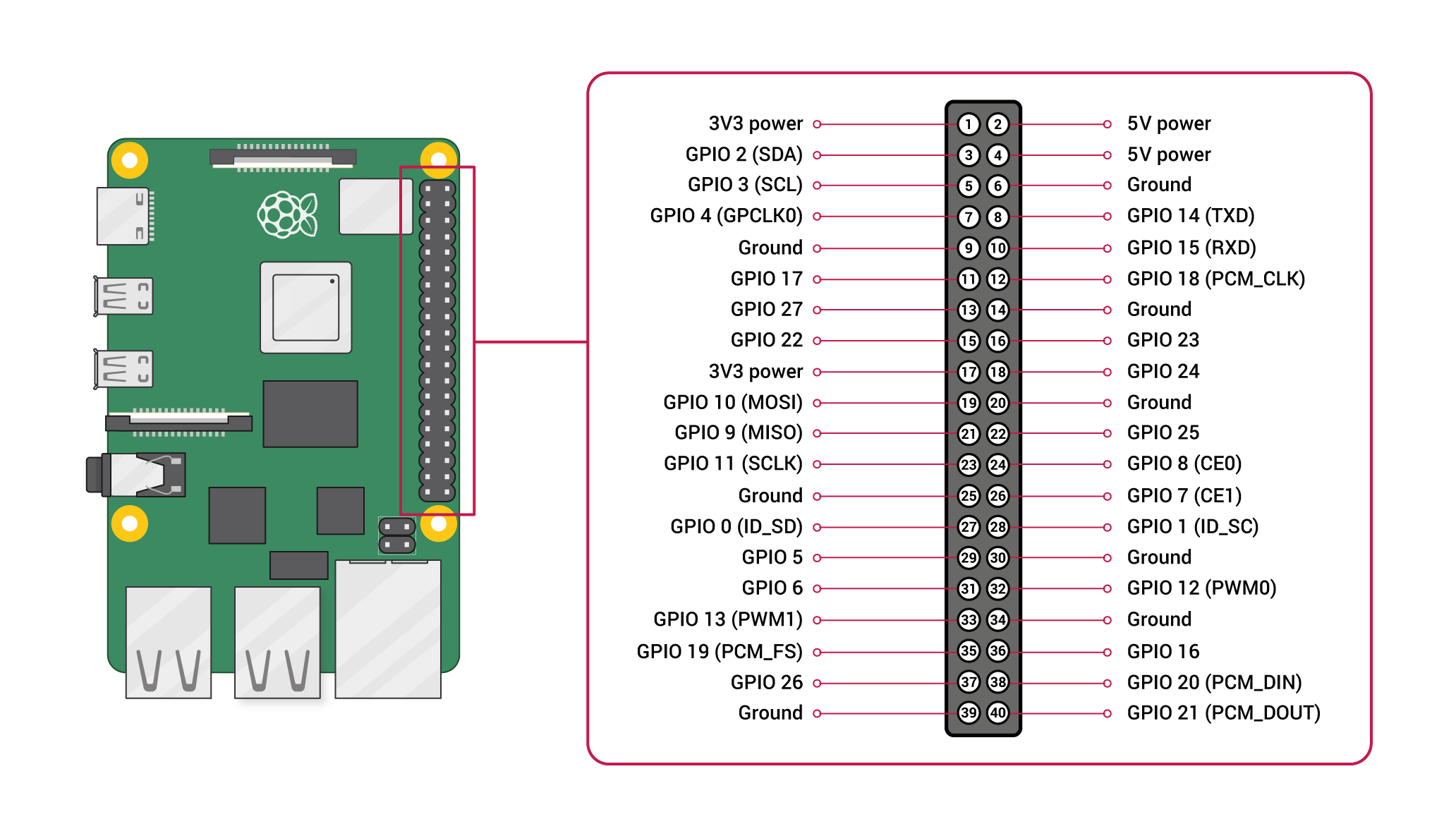
For both the RaspberryPi and the Jetson Nano there are 3 pins that we will want to connect to the F9P to communicate between serial ports:
- RPi/Nano board pin 6 is ground
- RPi/Nano board pin 8 txd (serial transmit)
- RPi/Nano board pin 10 is rxd (serial receive)
Note that we do NOT connect any positive voltage. There is no need; the F9P board will be powered when it is connection to the USB port, so we do not need to power it through the serial pins. If your gps receiver does not have a USB port, you will need to power via the VCC pin; most chipsets use 3.3v and NOT 5v, so make sure your USB to UART adapter can be set to use 3.3v.
Lefebure NTRIP Client for Android 🔗
Lefebure offers a free NTRIP client and NMEA data logger for Android.
With the Android NTRIP client, your phone connects to the NTRIP server and then sends the RTCM corrections via a Bluetooth. The gps receiver can get the corrections in one of two ways.
- If the receiver has a bluetooth radio connected to its serial port, then the phone would be paired to that radio and the corrections would go directly from the phone to the gps receiver via the bluetooth radio.
- If the receiver is connected to a RaspberryPi or Jetson Nano, then the RPi/Nano would pair to the phone and the corrections would go from the phone to the RPi/Nano via bluetooth. The RPI/Nano would then forward to the gps receiver using RTKLIB and str2str as previously explained.
Configure Android NTRIP Client 🔗
- Install Lefebure NTRIP client for Android from the android store or from http://lefebure.com/software/android-ntripclient/
- Configure the NTRIP source on Lefebure NTRIP client
- Configure the NTRIP settings to connect to your NTRIP server. Note that the application wants an ip address, not a url. You can usually get the ip address either from the organization’s website, or just run the
pingcommand with the server’s url and it will usually yield the ip address.$ ping rtgpsout.unavco.org PING saturn.unavco.org (69.44.86.36): 56 data bytes Request timeout for icmp_seq 0 - See how it resolved
rtgpsout.unavco.orgto the ip address69.44.86.36.
- Configure the NTRIP settings to connect to your NTRIP server. Note that the application wants an ip address, not a url. You can usually get the ip address either from the organization’s website, or just run the
Once you setup the NTRIP caster, you can connect in ‘test’ mode (no receiver) to see if the client will connect and that you can read corrections. Once you know you are getting corrections, then yo can configure a receiver that will get them.
- Configure the receiver settings. You may need to do this after pairing the RaspberryPi and the phone (steps 1, 2 and 3 below) so that the raspberrypi device can be selected in the
Bluetooth Devicefield.Receiver Connectionshould be ‘External via Bluetooth’Bluetooth Deviceshould be `raspberrypi’ (or whatever the nano device is named if using a nano)- Leave the other fields to the defaults.
With both the NTRIP caster and the receiver configured, you can `Connect’. It should connect to the ntrip server and then transmit the corrections to the receiver.
Pair RPi/Nano and Phone over Bluetooth 🔗
Bluetooth pairing (steps 1, 2 and 3 below) needs to be done only once on the Raspberry Pi to set it up to connect to the Android Bluetooth. The process was adapted from what I found in this video: https://www.youtube.com/watch?v=sY06F_sPef4
- Setup Raspberry Pi for serial over bluetooth (SPP). Add the SP profile to the Pi; edit
/etc/systemd/system/dbus-org.bluez.service. In the editor, add the compatibility flag-Cto the ExecStart line. If necessary, add a second line that starts the serial port (SP) service which enables serial-over-bluetooth. NOTE: if you don’t want the serial port service to start on every reboot, then leave this line out, in which case you will need to start the serial port service manually before connecting the phone (see step 4 below). The two lines in yourdbus-org.bluez.serviceconfiguration should like the example below. When satified, save the file and reboot the RaspberryPi so the change takes affect.ExecStart=/usr/lib/bluetooth/bluetoothd -C ExecStartPost=/usr/bin/sdptool add SP - With serial-over-bluetooth enable, use the bluetoothctl command to pair and trust the phone
- On the the Android phone, start bluetooth pairing mode (look for new bluetooth devices)
- On the RPi, open a command prompt and start the bluetooth control application by entering
bluetoothctl. You will be placed in the bluetoothctl shell. - Run the
agent-oncommand (typeagent onand enter). - Run the
default-agentcommand. - Run the
scan oncommand to start looking for devices. It may take a minute, but you should see the phone appear; take note of the 48 bit MAC address that is displayed; the MAC address will look something like00:4d:e9:79:eb:a6 - Run
scan offonce you have this information. - Run
pair <MAC>, replacingwith the device’s MAC address. - Once paired, in the future you just have to connect, not pair. So in the future just run
connect <MAC>if the connection does not happen automatically. - Run
trust <MAC>so we don’t have to do this again in the future. - Run
paired-devices. You should see the Android phone in the list of paired devices. - Run
quitto exit the bluetoothctl shell.
Send corrections from phone to RPi/Nano 🔗
Send corrections from the Android NTRIP client to the RaspberryPi or the Jetson Nano.
- Now that RPi and your phone are paired, connect the NTRIP app.
- On the RaspberryPi, if you did not configure the serial port service to start on every reboot (see step 1 above), then start it now;
- Run
sudo sdptool add SPat the command prompt. You should get “Serial Port service registered”
- Run
- Start the RaspberryPi listening for a connection on bluetooth serial so it will automatically connect when the Android phone is available.
- Run
sudo rfcomm watch hci0.
- Run
- In the Lefebure NTRIP app, choose
Connect. - In the RPi command prompt you should see should it connect on a bluetooth serial port (
/dev/rfcomm0in the example below):pi@raspberrypi:~ $ sudo rfcomm watch hci0 Waiting for connection on channel 1 Connection from 00:3D:E8:89:EA:B6 to /dev/rfcomm0 Press CTRL-C for hangup
- On the RaspberryPi, if you did not configure the serial port service to start on every reboot (see step 1 above), then start it now;
- Now we can run RTKLIB str2str in a separate command console on the RPi to route the incoming NTRIP to the F9P (in the case below, via the second hardware serial port that has been enabled on the GPIO bus; see details below).
./str2str -in serial://rfcomm0:115200:8:n:1 -out ./rtcm.txt -out serial://ttyAMA1:115200:8:n:1
At this point corrections will be read by the phone, then sent via bluetooth to the RPi and then sent via serial to the gps receiver. The receiver should go into float (blinking LED) and then fixed (LED off) mode.
DonkeyCar 🔗
DonkeyCar is the open source framework I use for racing autonomous RC cars. I’m also a maintainer on the project. I list it here because I wrote a gps driver for it (a ‘part’ in DonkeyCar parlance) that reads NMEA sentences from a gps receiver and parses out the position. It’s very rudimentary at the moment; GpsPosition simply provides the most recent position in UTM units (effectively the position on Earth in meters rather than in latitude and longitude). GpsPosition actually uses the Gps class underneath, which is a gps datalogger that returns all the positions (and their timestamps) recorded since the last call. As I need more it will get better. For instance, I know I’ll want to start returning the vehicle’s heading as measured by the receiver. I may also want to get measures of the quality of the position estimate.
The important part for this discussion is the __main__; it provides a command line utility that can be used to log positions and record waypoints.
- Install DonkeyCar on your RaspberryPi or Jetson Nano
- Make sure you are in the donkeycar project folder (where you cloned the code).
- Activate the donkeycar python environment if it is not already;
source ~/env/bin/activate - Run the gps part in logging mode.
- The
<serialport>value differs depending on how you have your gps receiver connected (by usb or gpio serial) and by SBC (RPi vs Nano)- You can list all potential serial ports;
ls /dev/tty*. Note that most of these are actually not usable. - If connecting to the Nano USB port, use
/dev/ttyUSB0. - If connecting to the RPi USB port, use
/dev/ttyACM01. - If connecting to the default RPi gpio serial port (board pins 8&10) use
/dev/ttyAMA0. - If connecting to the default Jetson Nano gpio serial port (board pins 8&10) use
/dev/ttyTHS1.
- You can list all potential serial ports;
- The
<baudrate>value differs depending on your gps and if you have changed it using U-Center.- when connecting between the SBC’s USB port and the usb port on the gps receiver the baud rate is detected by USB, so choose 115200 so you have a fast connection.
- The ZED-F9P’s other serial ports default to 38400 baud.
- Cheap gps receivers generally default to 9600 baud.
python donkeycar/parts/gps.py -s=<serialport> -b=<baudrate>
- The
- You can also collect waypoints and then the logging will indicate which waypoint your are within as you move around.
- after executing the following command, the software will wait for you to press the space bar before collecting the samples for each waypoint.
python donkeycar/parts/gps.py -s=<serialport> -b=<baudrate> -wp=<number of waypoints> -sp=<samples per waypoint>
- after executing the following command, the software will wait for you to press the space bar before collecting the samples for each waypoint.
- If you are running the Linux Desktop on the RPi/Nano (as opposed to ssh), then you can also add the
-dbargument. That will tell the software to render the waypoints and show them in a window. That only works if you are running the linux GUI; you can’t do that from an ssh session because it can’t show you the graphic window.
Feel free to leave an issue in the DonkeyCar github repo if you find a bug or want to suggest and improvement.
The Hardware: An Unexpected Journey 🔗

The plan at the start was to stream the RTCM3 corrections from the RaspberryPi or Jetson Nano’s default GPIO serial port to the ZED-F9P’s corrections port (F9P UART2). So the first thing that was needed was to solder the headers to the F9P so we can make physical connections using dupont jumper wires. I’m not going to go into that; there are a lot of videos on YouTube on how to solder headers and what you need to do it. My only suggestion is to practice a LOT before you try to solder headers to your $300 gps board. And have some flux ready.
Once gps headers are soldered then dupont jumper wires were connected from the computer’s default GPIO serial port on board pins 8&10 to the corrections serial port on the F9P. By default the ZED-F9P corrections port is configured to read RTCM3. The reason I started this way was because ‘default’ is a good word. Look at all those defaults. Nice. Or so I thought.
Wiring Connections We connect dupont jumper where been the F9P corrections port and the RPi/Nano default gpio port.
The F9P corrections port:
- TX2 is serial transmit
- RX2 is serial receive
- GND is ground
The 40 GPIO bus on the RaspberryPi or Jetson Nano:
- Board pin 6 is GND
- Board pin 8 is TX for uart2
- On the Jetson Nano the default spio serial port is
/dev/ttyTHS1. - On the RaspberryPi 4 the default gpio serial port is
/dev/ttyAMA1.
- On the Jetson Nano the default spio serial port is
- Board pin 10 is RX for uart2
After those are connected, then connect the RPi/Nano and ZED-F9P via a USB cable. So our fully connected setup looks like this:
RPi/Nano            ZED-FP9
-----------------------------
Pin-6        <--->  GND
Pin-8, TXD   <--->  RX2
Pin-10, RXD  <--->  RX2
USB          <--->  USB
Software setup (TLDR version)
- Use U-Center to set the FP9 UART-2 to 115200 baud
- Set the RPi/Jetson Nano serial port to 115200 baud
sudo stty -F /dev/ttyTHS1 115200 - Run str2str on the RPi to get corrections from UNAVCO or your NTRIP server and send them from the default gpio serial port to the FP9 corrections port.
./str2str -in ntrip://USERNAME:PASSWORD@rtgpsout.unavco.org:2101/P200_RTCM3 -out serial://ttyTHS1:115200:8:n:1 - Read NMEA messages on USB serial port, /dev/ttyACM0
The bad news is that with this setup I never get to float mode on the ZED-F9P using either the RaspberryPi or the Jetson Nano; the RTK LED on the Sparkfun ZED-F9P stayed solidly lit. Let me explain (isn’t that what this whole article is for?); the ZED-F9P goes through stages as it develops a more accurate position estimate. This is indicated by an LED on the Sparkfun ZED-F9P board labeled RTK. When it is solid it is not using any corrections and so the position estimate is at its least accurate. When it starts using corrections, but before most of its satellites are corrected, it is in ‘float’ mode. In this mode the RTK LED blinks. Float mode is more accurate, but more importantly it indicates that RTCM3 corrections data is getting to the ZED-F9P. If you have a good view of the sky and you never get to float mode then it probably means the RTCM3 corrections are not getting to the gps board correctly. Of course if you are in your basement then it doesn’t matter if the corrections make it to the board; you can’t see any satellites! If you get to float mode then the next stage you are hoping for is ‘fixed’ mode. In this mode the F9P can apply corrections to most of the satellites it can see and so its position estimate is optimal. In ‘fixed’ mode the RTK LED goes off. So, if the RTK is solidly lit, then things are not working.
So the bad news is that sending RTCM3 corrections from the RPi or Nano using the default gpio serial port does not seem to work. There is no error message from str2str; we just never get to float (and so never to fixed). But there is some good news; there is a simple work around. Even better, there is a difficult work around (see Where art UART oh RPi?). The easy work around should be obvious to the most casual observer (or to me after several days of trying to make the GPIO serial work); don’t try to send RTCM correction over the gpio serial; instead send them over the USB serial. Stupid. Simple. I got to ‘fixed’ on the Jetson Nano by streaming RTCM3 over the USB serial port. Reading the NMEA from the GPIO serial port works fine, so we are set there. Even better news, in 100 samples I got a range of 2.5 cm. Notice the ‘c’ before that ‘m’. If it ain’t broken, it’s fixed and fixed is good.
This the str2str command that worked; it gets the corrections from and NTRIP server over the internet and then sends then to the ZED-F9P via USB serial.
./str2str -in ntrip://USERNAME:PASSWORD@rtgpsout.unavco.org:2101/P200_RTCM3 -out serial://ttyACM0:115200:8:n:1
- Since we are sending the corrections via the serial port, then we need to read the NMEA sentences on a different port. We can read NMEA messages from the GPIO serial port (
/dev/ttyTHS1on Nano or/dev/ttyAMA0on the RPi) connected to the ZED-F9P corrections port that we setup earlier.
Where art thine UART oh RPi? 🔗
As previously discussed ad nauseum, I have found that UART on the GPIO bus (gpio 14&15 exposed on board pins 8&10 respectively) to be unreliable; it is not based on a hardware UART and so it is more prone to issues at higher speeds. That bugged me, so even though I found a work around, I wanted to fix it. I have not found a fix on the Jetson Nano, but it can be fixed on the RaspberryPi 4 (but not RPi 3 or below; sorry). By default the RPi uses two UARTs; one for the bluetooth functionality and one for the GPIO serial port. The Bluetooth UART uses underlying hardware and so can handle very high baud rates with hardware handshaking. The UART exposed on the GPIO bus is less capable. Luckily the RPi 4 actually has 6 hardware-based UARTS. We can expose these by using device-tree overlays. The device tree is data that is loaded at boot time that tells Linux which devices are attached and so which drivers to load. A device tree overlay (dtoverlay) is a way of adding to the device tree without having to create a whole new one. RaspberryPi OS has a bunch of available dtoverlays that can be used to turn on optional features. We can list the ones that have to do with UARTs (see this RPi forum discussion)
$ dtoverlay -a | grep uart
  midi-uart0
  midi-uart1
  miniuart-bt
  uart0
  uart1
  uart2
  uart3
  uart4
  uart5
It so happens that the uart3 will enable a hardware uart on a couple of gpio pins that we are not already using. To to enable uart3 on the gpio bus, add this to the /boot/config.txt file, in the [pi4] section (you will need to sudo), then reboot.
# Enable UART3 on gpio 4=tx & 5=rx, no flow control pins
dtoverlay=uart3
Once that is done, then the serial device /dev/ttyAMA1 can be used to control the UART exposed on gpio 4&5, which are exposed on the 40 pin bus on board pin 7 and board pin 29 respectively.
Connections when using the RaspberryPi4 UART3
RPi            <--->  FP9
--------------       ----------
Pin-9  (GND)   <--->  GND
Pin-7  (GPIO4) <--->  UART2-RX
Pin-29 (GPIO5) <--->  UART2-TX
USB            <--->  USB
Um, does this !@#$% actually work? 🔗
I’m shocked you had to ask. After months of work I finally got a gps auto-pilot running in the Donkeycar framework. I decided that I did not want to purchase a second RTK receiver to use as a base station, plus the necessary radios, and I did not want to rely on anyone else’s base station. Instead, I mounted my phone on the car; I added a platform under the main platform to hold the phone wrapped in packaging foam (see A GPS Donkeycar for a side view of the car). I put the phone in wifi-hotspot mode and then paired my RaspberryPi to the phone’s wifi hotpspot. So during the race the RaspberryPi has internet wherever it goes (as should we all).
I got this all working 2 days before the July Diyrobocars race. That turned out to be an interesting set of races. We had about 7 competitors show up, of which 4 got their cars to run. One the 4 runners crashed out during a warm-up lap, so we ended up with 3 competitors. They ran 3 different software stacks; all based on great open source projects. One was an F1Tenth based car running ROS. Another was based on Ardurover software running on a Pixhawk controller. My entry was running a Donkeycar branch on a RaspberryPi 4B.
The race was epic. It was everything you want from motorsports; passing, crashing and a come-from-behind win. The Donkeycar entry ended up in second place after being wiped out by the winner; the superfast (and large) ROS entry. Notice how the Donkeycar recovers after being completely turned around in the crash.
Now that Donkeycar has the ability to race outside I hope that we will see a lot more competitors in our future races.
Status of the Donkeycar branch 🔗
The branch has been merged into the main Donkeycar branch. I’m currently working on documentation in this donkeydocs branch.
Thanks, but is there someone around here that knows anything? 🔗
ArduSimple makes gps boards and has excellent content.
Sparkfun makes lots of great stuff, including gps boards. They are known for their excellent content explaining how to use their products.
Here is a good video from someone that uses the F9P RTK receivers to drive an autonomous lawn mower. He goes though 3 or 4 different kinds of configurations using U-Center.
Here are a few videos I made regarding this subject.